
CloudFlare Railgun on AWS
Notice: This article is more than 8 years old. It might be outdated.
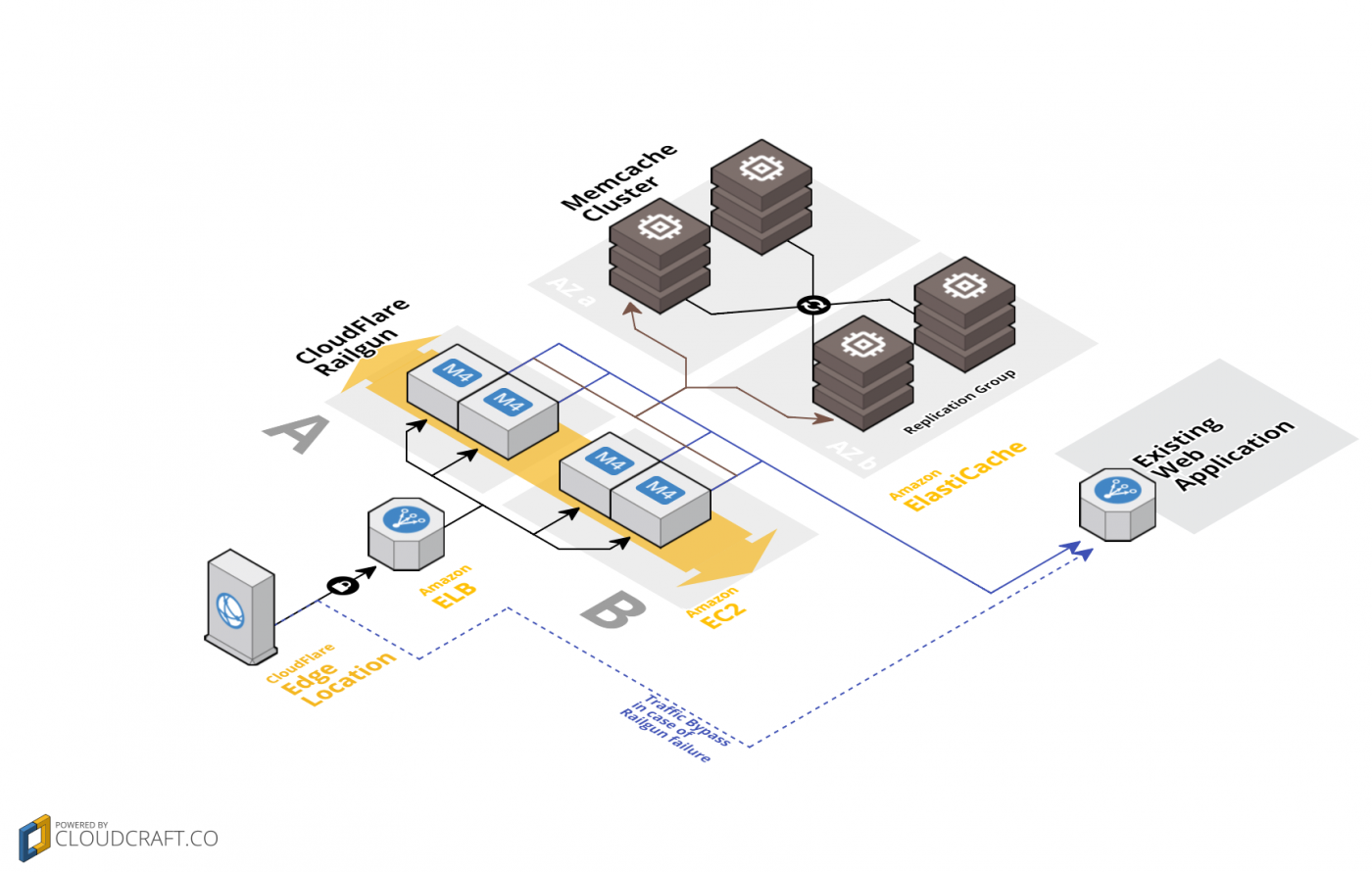
This tutorial will show you how to configure CloudFlare Railgun within Amazon Web Services (AWS). We will leverage Amazon ElastiCache together with AWS Elastic Load Balancing, AWS Auto Scaling and Amazon EC2 to quickly and simply achieve this goal (See Figure 1).
This setup should especially be appealing to CloudFlare customers, operating their origin servers in one or more Amazon Web Services (AWS) regions, and who want to leverage the power of AWS to compensate automatically against failures of the CloudFlare Railgun Listener application.
About CloudFlare Railgun
CloudFlare Railgun accelerates the connection between each CloudFlare point-of-presence (PoP) and a customer origin server so that requests that cannot be served from the CloudFlare cache are nevertheless served very fast. By leveraging techniques similar to those used in the compression of high-quality video, Railgun compresses previously uncacheable web objects up to 99.6%.
Railgun consists of two software components: the Listener and Sender. The Railgun Listener is installed on a server close to the customer origin server, or in some cases on the origin server itself. It’s a small piece of software that runs on a standard server and services requests from CloudFlare using the encrypted, binary Railgun protocol. Railgun Listener is a single executable whose only dependency is a running Memcache instance. It runs on 64-bit Linux and BSD systems as a daemon.
The Listener requires a single port (TCP/2408) open from the Internet for the Railgun protocol so that CloudFlare PoPs can contact it. And it requires access to the website to be accelerated via HTTP and HTTPS. The website still needs to be accessible over ports TCP/80 and TCP/443 by the CloudFlare PoPs, as a fallback path in case of Railgun experiencing any issues.
Ideally, the Listener would be placed on a server with fast access to the Internet and low latency. Installation is simply a matter of installing via an RPM or .deb file.
Railgun is available for customers with a CloudFlare Business or Enterprise plan or customers hosted with an Optimized Hosting Partner.
Setup Overview
As outlined in Figure 1, the setup will consist of the following elements:
- Amazon Virtual Private Cloud (VPC): Provide network isolation with a public subnet to operate the Railgun nodes and a private subnet to operate the Railgun to Memcached connection.
- Amazon ElastiCache: A managed Memcached cluster to fulfill the Railgun requirements. The cluster can contain one or more nodes.
- AWS Elastic Load Balancing: A managed load balancer to distribute traffic across multiple Railgun instances within the same AWS region.
- AWS Auto Scaling: Automatically replace failed Railgun instances.
- Amazon EC2: Run a 64-bit Linux and automatically install the latest version of CloudFlare Railgun.
The following sections walk you step-by-step through the setup. In this example we will use a Memcached cluster with 2 nodes, spread across two AWS Availability Zones, as well as 2 Railgun nodes, spread across two AWS Availability Zones. While this setup will provide ideal redundancy, it might not suit your direct business needs. Therefore please adapt the setup accordingly.
VPC Setup
We will use Amazon Virtual Private Cloud (VPC) to provide network isolation. The Railgun nodes will be placed on two public network segments, so that they are reachable from the public Internet and therefore from the CloudFlare PoPs. Two private network segments will be used for traffic between the Railgun nodes and the ElastiCache based Memcached instances.
Two security groups, one for Railgun and one for ElastiCache, will be used to ensure that only valid traffic can reach the nodes.
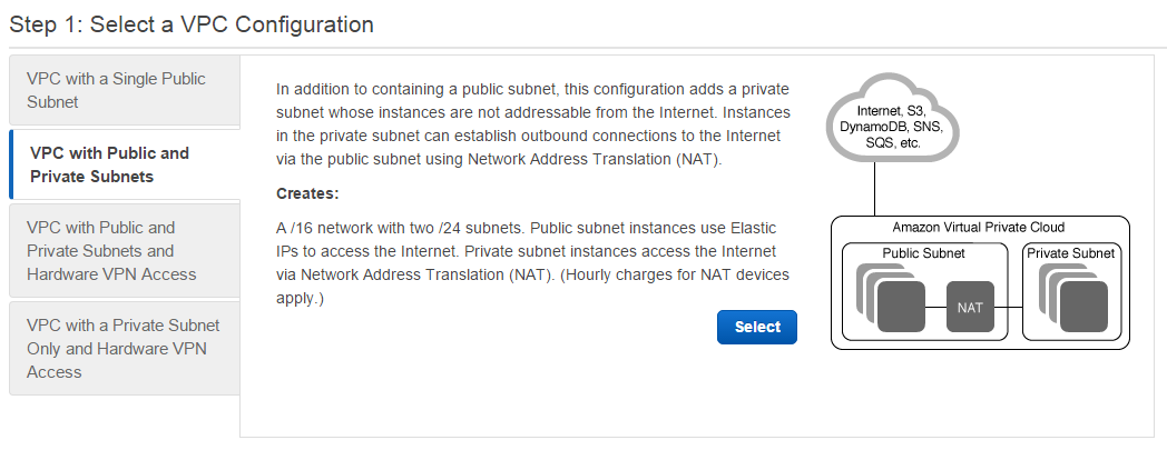
Let’s get started by creating a VPC of type VPC with Public and Private Subnets (See Figure 2).
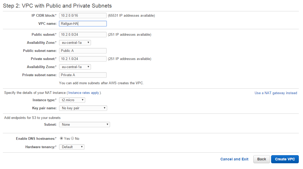
Choose your preferred IP CIDR block and provide a meaningful VPC name, such as Railgun-HA. Consciously pick an Availability Zone for both subnets and include the AZ identifier in the subnet name. This will later help you identify which subnet is used for what purpose and resides in what AZ. For the NAT instance information chose Use a NAT gateway instead (see Figure 3).
The VPC template for VPC with Public and Private Subnets will only create a single public and private subnet. But we will want to leverage two public and two private subnets, across two AZ in order to build a true highly available solution. Therefore we now need to create another public and private subnet within the VPC.
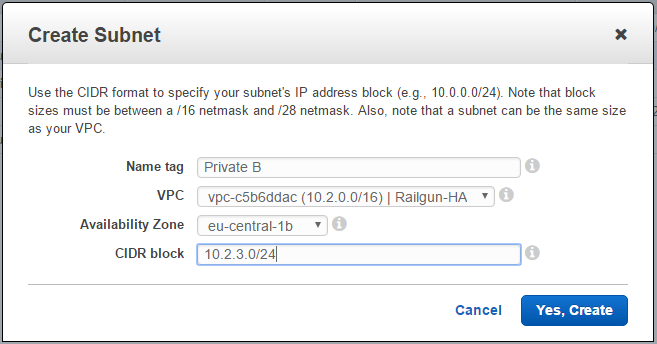
Let’s start by creating another public subnet. Pick a different AZ to the one that was selected when creating the VPC. Also try to come up with a pattern for assigning the CIDR blocks. Here I use even numbers for the third octet in case it is a public subnet and uneven numbers in case it is a private subnet (See Figure 4).

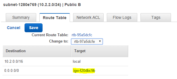
In order to make the newly created subnet a public subnet, you have to change the routing policy, so that the destination 0.0.0.0/0 points to an internet gateway, which is indicated via the target name prefix of igw (See Figure 5).
Next create another private subnet. Here also pick a different AZ to the one that was selected for the first private subnet when creating the VPC (See Figure 6).
After successfully creating all the necessary subnets, it’s time to create the security groups. One will be used to allow Railgun traffic and another one will be used to allow Memcached traffic.
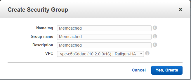
Let’s start by creating the Security Group for Memcached traffic (See Figure 7).
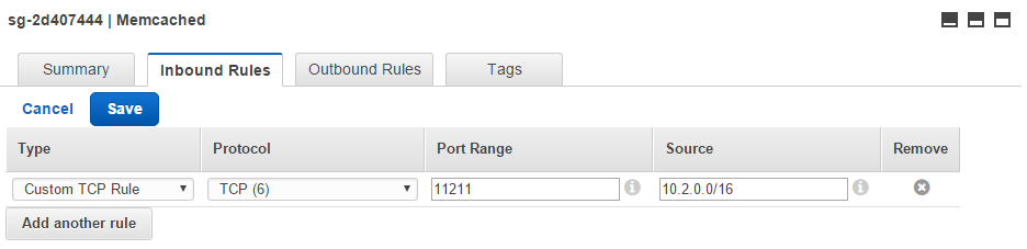
For the newly created Memcached security group, add an Inbound Rule. Select “Custom TCP Rule” with the protocol TCP and the port range 11211. As the Source you can select the IP range of your newly created VPC or limit it even further to the public subnets (See Figure 8).
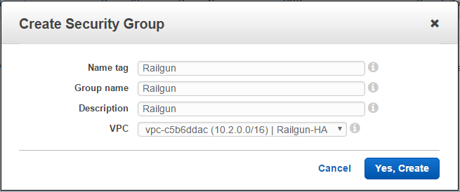
Next, create a Security Group for Railgun traffic (See Figure 9).
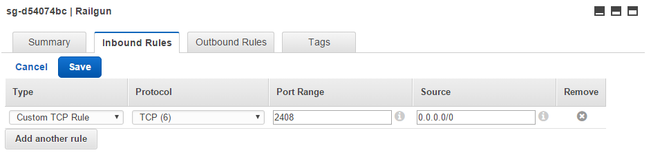
For the newly created Railgun security group, add an Inbound Rule. Select “Custom TCP Rule” with the protocol TCP and the port range 2408. As the Source you can select 0.0.0.0/0 to open up access to all of the public Internet. As an alternative you could limit access even further to the CloudFlare IP ranges only (See Figure 8).
This completes the setup steps for the VPC and the Security Groups.
ElastiCache Setup
One of the pre-requisites for running CloudFlare Railgun is access to Memcached. ElastiCache provides us a managed Memcached cluster. While a Memcached cluster does not provide full protection against the failure of a cluster node, the impact of such a failure would at least be compensated. In case of a two node cluster, only approximately half of the keys would be lost in case one node fails.
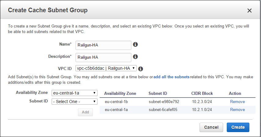
In this tutorial we will create a two node ElastiCache cluster with the engine Memcached. Before we can do this, we need to create a Cache Subnet Group. A Cache Subnet Group attaches the nodes of an ElastiCache cluster to a certain VPC subnet. Here we want to attach our ElastiCache cluster to the private subnet, that we created in the previous step.
Lookup the subnet IDs for the two private subnets that you created and start the creation of the Cache Subnet Group. Pick the VPC that you created, and for each of the two Availability Zones, specify the two private subnets (See Figure 11).
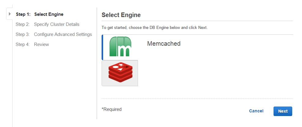
Next start the creation of a new ElastiCache cluster and chose the engine type “Memcached” (See Figure 12).
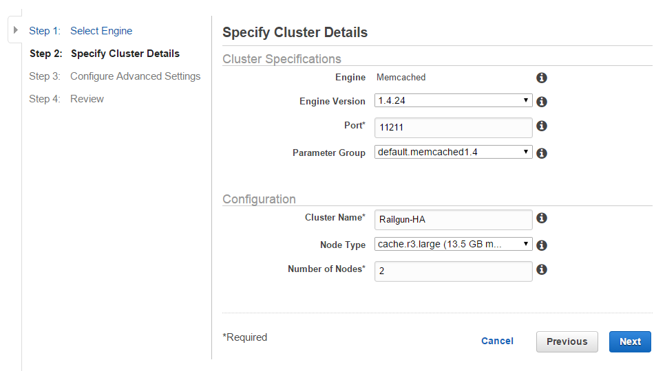
Chose the node type depending on your performance needs and select the number of nodes that you want in your cluster. In this example we will use 2 nodes, in order to achieve a certain level of redundancy (See Figure 13).
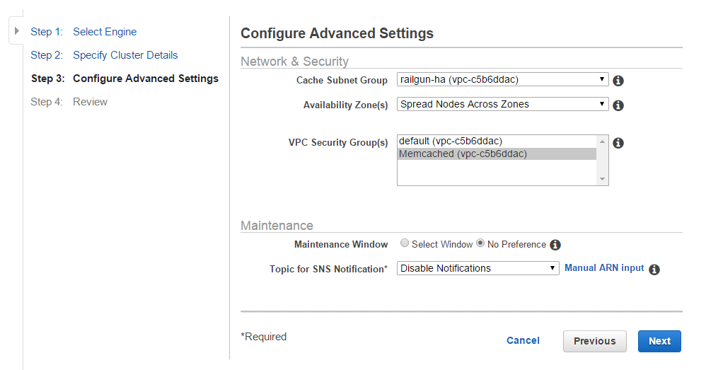
Select the Cache Subnet Group that you created at the beginning of this section. Use the Availability Zone policy of “Spread Nodes Across Zones”. This will ensure that in case of a Availability Zone failure, you still have one ElastiCache node left. For the VPC Security Group select the “Memcached” security group that you created (See Figure 14).
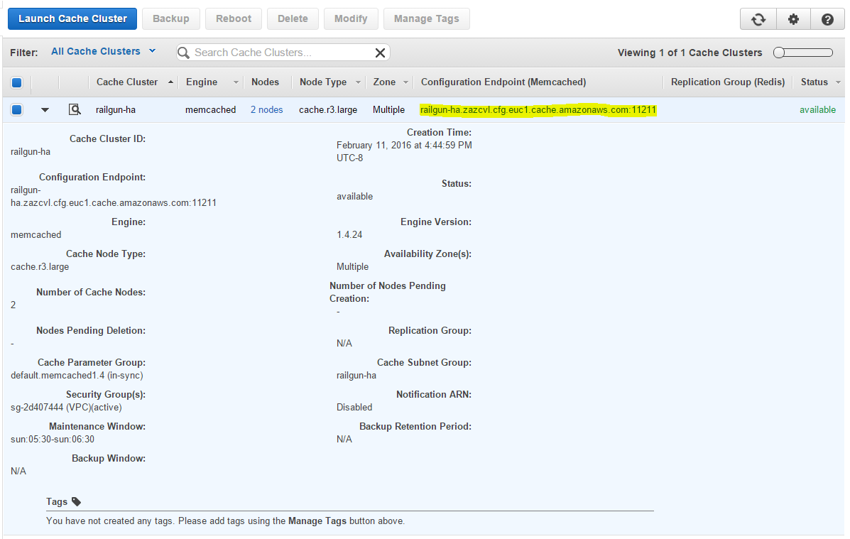
Wait for the ElastiCache cluster to be created and note down the configuration endpoint address (See Figure 15). You will need this address in a later step.
This completes the setup steps for the ElastiCache Memcached cluster.
Elastic Load Balancer (ELB) Setup
The Elastic Load Balancer (ELB) serves the purpose of distributing incoming traffic from the CloudFlare PoPs among the active Railgun nodes. As the ELB and its hostname serve as the termination point for CloudFlare Railgun traffic, it is very simple to replace a failed Railgun node behind the ELB, without making any configuration changes to the Railgun setup.
This configuration also allows to scale out the number of Railgun nodes or scale up the size of the Railgun nodes, without impacting production traffic.
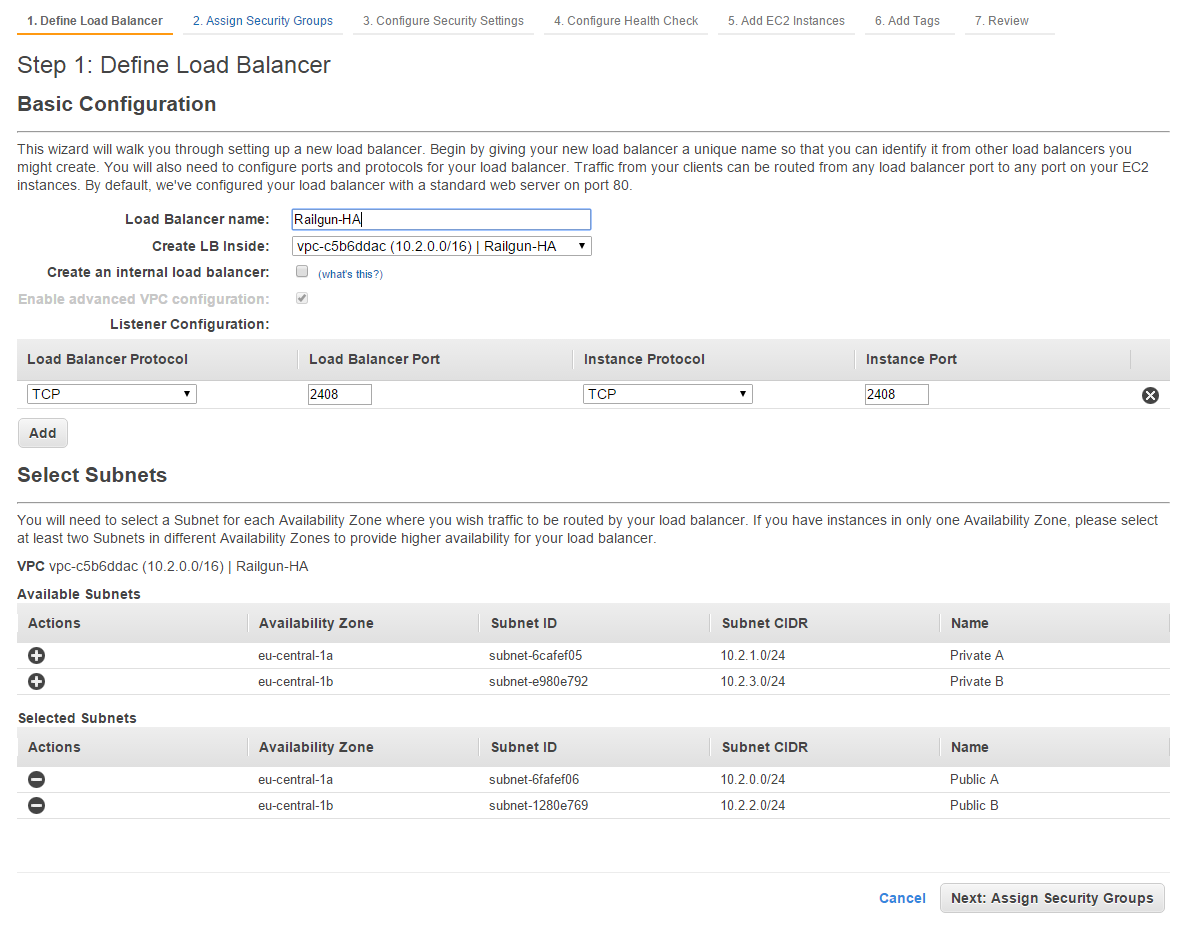
Create a new ELB inside the VPC that you are using for the Railgun setup. For the Listener Configuration chose TCP as the Load Balancer as well as Instance protocol. Enter “2408” as the Load Balancer and Instance port. For the subnets, select the two public subnets that you created earlier (See Figure 16).
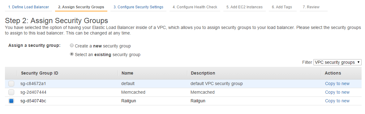
Next assign the security group Railgun, which you have created in an earlier step. This will ensure that only Railgun traffic is allowed through the ELB (See Figure 17).
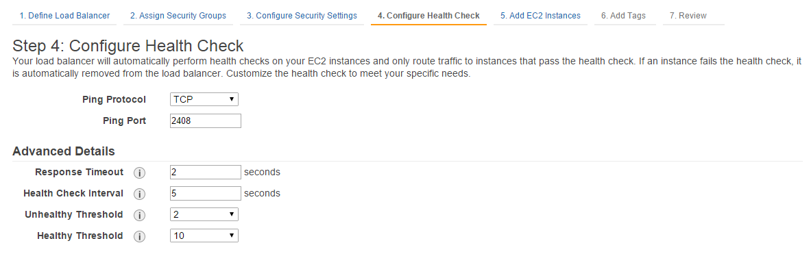
Next, configure the Health Check. This will determine how the ELB will probe the Railgun nodes and determine whether they are healthy. As the ping protocol select TCP with the ping port of 2408. This is necessary as the protocol between Railgun Listener and Railgun Sender is a binary protocol and not HTTP or HTTPS. Under Advanced Details you can reduce the timeout, interval and thresholds to the minimum values for a fast failover reaction (See Figure 18).
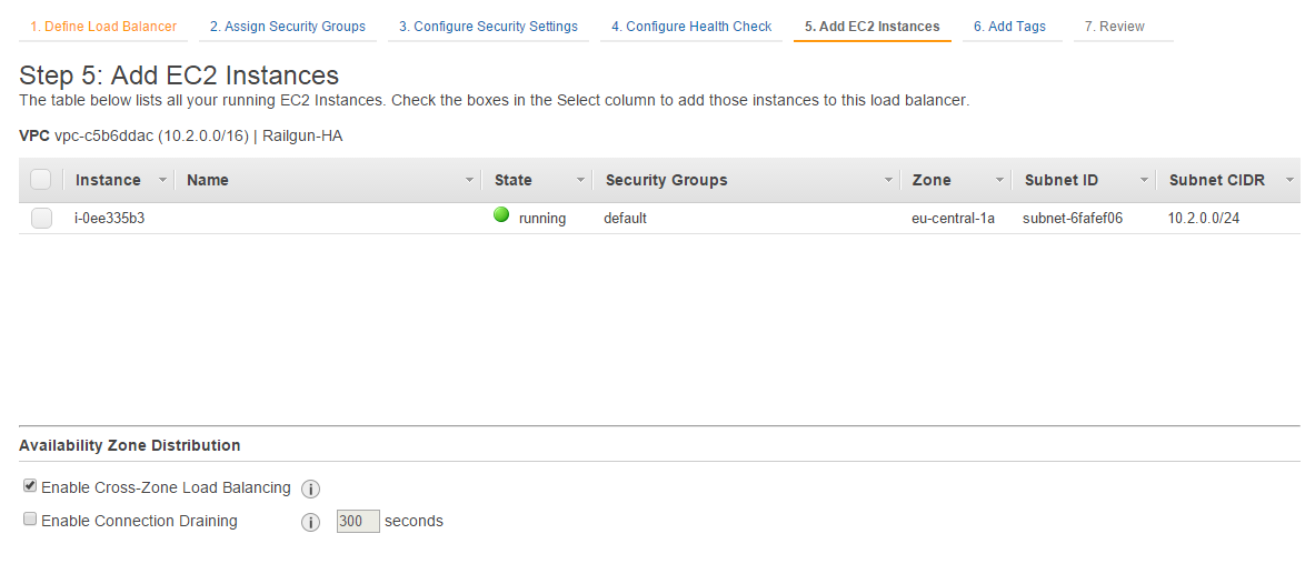
In the next step you would add the various instances to the ELB. As we have not yet created any Railgun instances, we will not add any instance here.
Instead we will solely ensure that the box for “Enable Cross-Zone Load Balancing” has been ticked (See Figure 19).
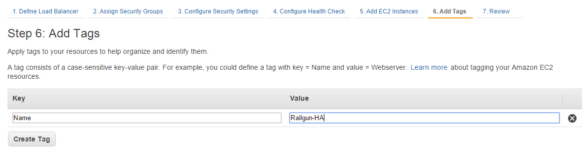
You can tag the ELB with a name (See Figure 20).
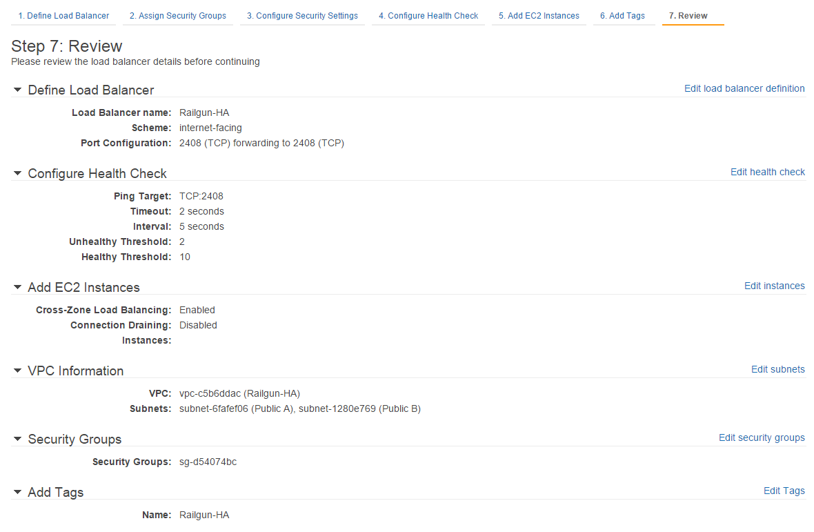
Before completing the creation of the ELB, you can validate that all settings have been configured correctly (See Figure 21).
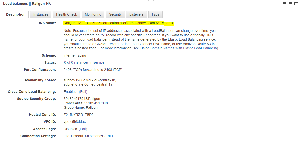
Once the ELB has been created successfully, lookup the DNS name and note it down (See Figure 22). You will need it in a subsequent step.
This completes the setup steps for the Elastic Load Balancer (ELB).
Auto Scaling Setup
In this setup we will use Auto Scaling primarily to automatically replace failed Railgun instances. To do so, we configure an auto scaling group with a minimum of 2 instances.
Part of the Auto Scaling configuration is a launch group, where instead of using a pre-built Railgun AMI, we will built a Linux OS with the latest Railgun version on the fly. This will dramatically reduce the overhead for managing and updating custom OS images.
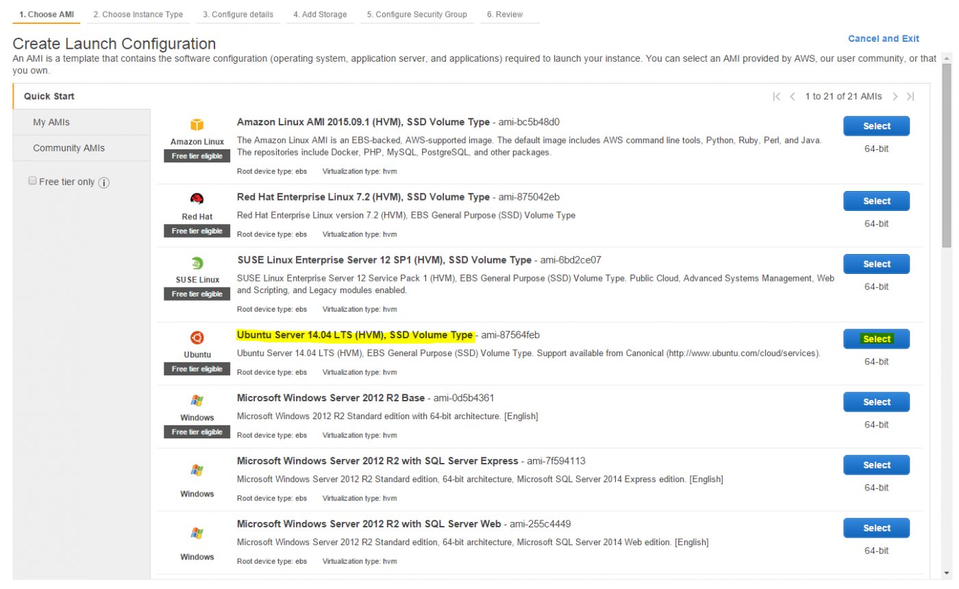
Start by creating a Launch Configuration, where you select the latest Ubuntu Server LTS version as your prefered AMI (See Figure 23).
As mentioned we will instruct the launch configuration to install and configure the latest version of CloudFlare Railgun on the fly. This can be done via the EC2 Cloud Init method, where we pass a shell script into the newly created Linux OS.
Below is the script that will be executed upon boot. It will install and configure CloudFlare Railgun. You will have to replace three values within the script:
- Railgun Activation token: You can find this token within the CloudFlare Web UI.
- Railgun Host: The hostname of the ELB. You should have noted this down in an earlier step.
-
Memcached Server: The hostname of the ElastiCache Memcached cluster. You should have noted this down in an earlier step.
#!/bin/bash echo ‘deb http://pkg.cloudflare.com/ ‘
lsb_release -c -s’ main’ | tee /etc/apt/sources.list.d/cloudflare-main.list curl -C - https://pkg.cloudflare.com/pubkey.gpg | sudo apt-key add - apt-get update apt-get install -y railgun-stable sed -i “s/memcached.servers = 127.0.0.1:11211/memcached.servers = railgun-ha.zazcvl.cfg.euc1.cache.amazonaws.com:11211/” /etc/railgun/railgun.conf sed -i “s/activation.token = YOUR_TOKEN_HERE/activation.token = 123a4567bc123d4e567abcd89012345a/” /etc/railgun/railgun.conf sed -i “s/activation.railgun_host = YOUR_PUBLIC_IP_OR_HOSTNAME/activation.railgun_host = Railgun-HA-1142856350.eu-central-1.elb.amazonaws.com/” /etc/railgun/railgun.conf service railgun start
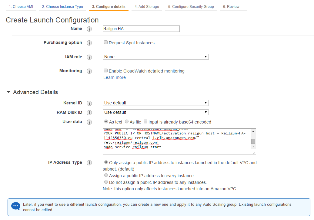
Give your Launch Configuration a name and paste the above script into User Data field (See Figure 24).
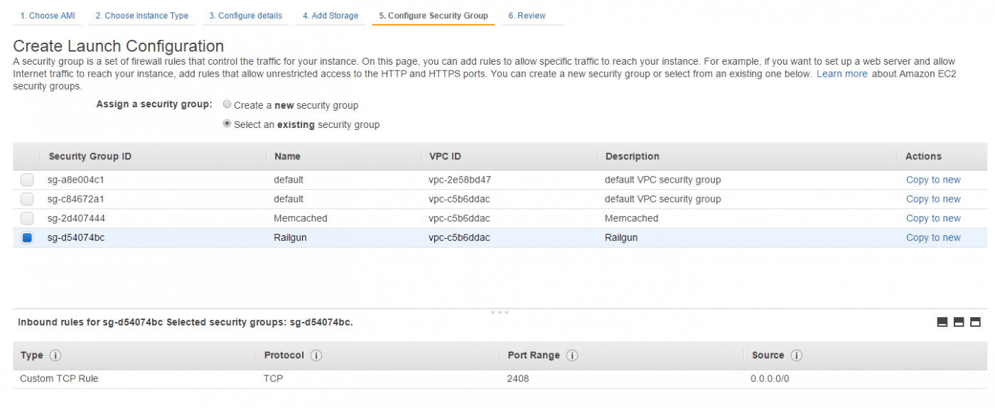
Within the Security Group configuration step, select the existing security group “Railgun” (See Figure 25). You have configured this security group in a previous step.
Next we have to create the Auto Scaling Group, which ties the Launch Configuration, Elastic Load Balancer and VPCs together to automatically launch the Railgun nodes.
Under Network chose the VPC that you are using for this Railgun setup and under subnet select the two public subnets of the VPC.
Select the ELB that you configured under Load Balancing and pick ELB as the Health Check Type (See Figure 26). This will ensure that Railgun nodes that do not accept connections over TCP/2408 anymore are considered unhealthy, will be terminated and replaced.
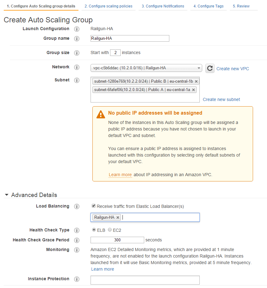
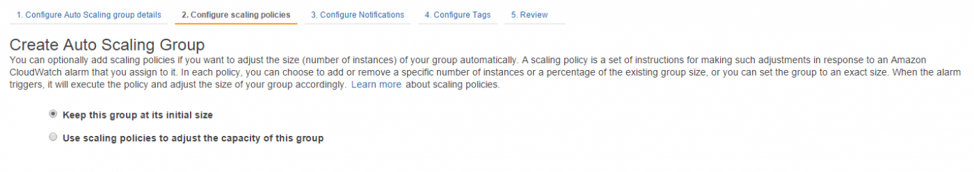
As we are solely using the Auto Scaling capability to replace failed Railgun nodes, pick “Keep this group at its initial size” for the scaling policy (See Figure 27).
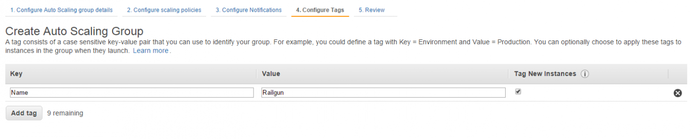
Next provide what tags you want to apply to all EC2 instances that are created as part of the Auto Scaling group. It is highly recommended to at least define the tag “Name” (See Figure 28).
This not only concludes the configuration of the Auto Scaling setup, but of your entire setup. AWS should now automatically spin up EC2 images, automatically install and configure CloudFlare Railgun inside of them and add them to the ELB load balancer. Have a look at the next section for learning how to test your setup.
Testing the setup
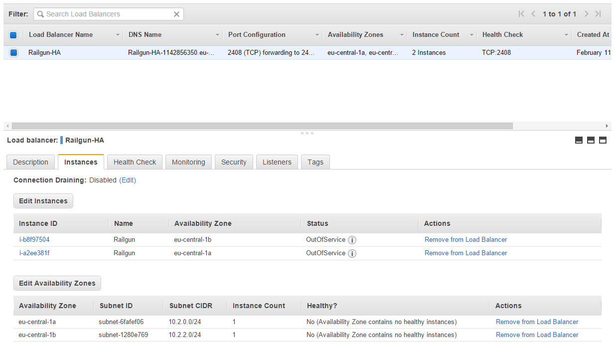
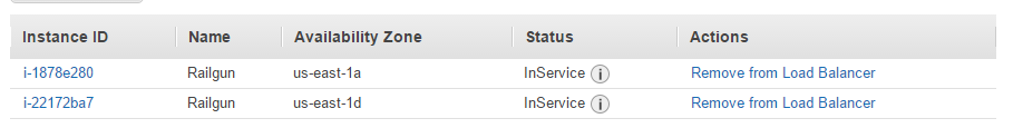
Now, with the setup in place it’s time to wait for the Railgun nodes to boot up and configure correctly. You can head over to the ELB setup and look at the instances under the configured load balancer. While the nodes are still initializing you should see the status “OutOfService” displayed (See Figure 29).
After a few minutes the status of the instances should change to “InService”, indicating that the Railgun Listener nodes are up and running and accept traffic over port TCP/2408 (See Figure 30).
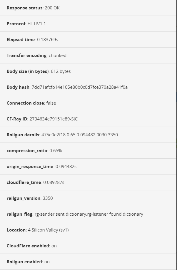
Now you can login to the CloudFlare Dashboard and test the Railgun setup. If everything is working you should see a “compression_ratio”, as well as “origin_response_time” displayed (See Figure 31).
Summary
This tutorial showed you how to use Amazon Web Services (AWS), with the services Amazon ElastiCache together with AWS Elastic Load Balancing, AWS Auto Scaling and Amazon EC2 to quickly and easily setup a highly available CloudFlare Railgun Listener setup.
Leave a comment