OpenStack with vSphere and NSX - Part 5: Create virtual networks and launch a VM instance in OpenStack
Notice: This article is more than 11 years old. It might be outdated.
Welcome to part 5 of the series: “OpenStack with vSphere and NSX” on installing OpenStack with VMware vSphere and VMware NSX. This series shows the deployment of an OpenStack cloud that leverages VMware vSphere – along with it’s well-known enterprise-class benefits such as VMotion – as the underlying Hypervisor. In addition, network virtualization within OpenStack will be provided via NSX as a Neutron plugin. This allows the creation of virtual networks within OpenStack that consist of L2 segments and can be interconnected via L3 to each other or the outside world.
In the previous post: “OpenStack with vSphere and NSX – Part 4: Import and configure the VMware vSphere OpenStack Virtual Appliance (VOVA)” we completed the import and configuration of the VMware vSphere OpenStack Virtual Appliance (VOVA). In this article we will take our new cloud for a quick spin and see what we can do with it, creating virtual networks within OpenStack that consist of L2 segments and interconnecting them via L3 to each other or the outside world. Also we will create our first VM instance via OpenStack. In the next post we will then dig a bit deeper and look behind the scenes.
Initial Login to OpenStack
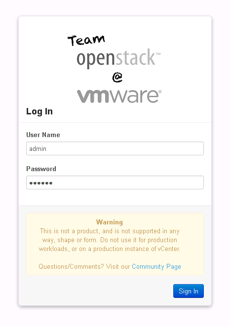
Let’s start with the initial login into OpenStack via VOVA. Point your preferred browser to the IP address or associated DNS name that you gave VOVA and login with the standard credentials. The username is admin and the password is vmware (See Figure 1).
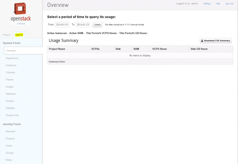
After successful login as the user admin you will end up in the admin view of the OpenStack Dashboard Horizon. This is the view that the operator of the OpenStack cloud would see and use (See Figure 2).
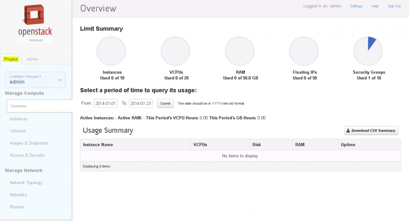
Let’s change over to the project view and see what a tenant would see. While the admin account allows you to see both, a regular tenant would only see the project view and not the admin view (See Figure 3).
Next, let’s have a look at the initial virtual network topology available to us. Click on the Network Topology tab within the Project area (See Figure 4).
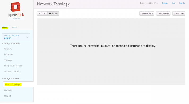
Initially the Network Topology is empty. This means that we do not have any network available to connect Virtual Machines to. As this situation is not very useful to us, let’s start by creating some networks. Here’s what we need at a base level (See Figure 5):
- An external (sometimes also called public) network that corresponds to the physical network segment providing us external connectivity.
- An internal network per tenant to which we can attach VMs. These per tenant VM can use this internal network to communicate with each other. But also we don’t necessarily want to connect every VM to the outside world.
- In order for the VMs, connected to the internal network, to reach the outside world (e.g. Internet) we also need a router providing Source NAT (SNAT) capability between internal and external network.
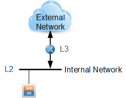
The first component will need to be provided by the cloud operator, while component 2 and 3 are created by the individual tenant. Let’s therefore consciously split these two jobs into their own sections.
Admin view
Creating an external network
As mentioned earlier the cloud operator of the OpenStack cloud will need to create the external network. The admin user that you are currently logged in with has the ability to perform operations as such a cloud operator. But we will later also use it to perform pure tenant operations.
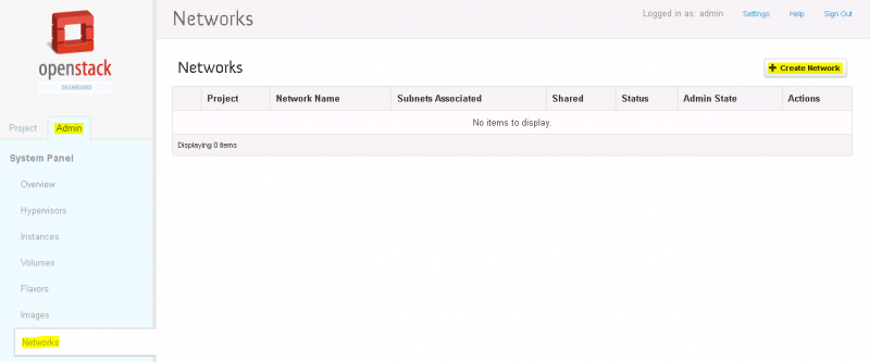
Return to the Admin view, choose the Networks tab and click on Create Network (See Figure 6).
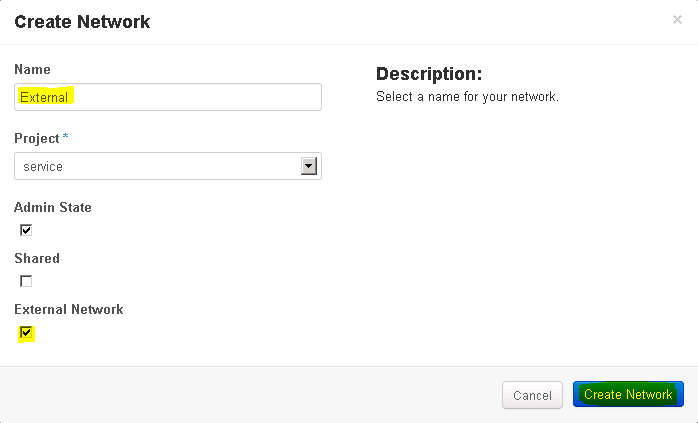
Give the new network a useful name such as External and tick the External Network box to designate it as an external network. You need to specify a project when you create a new network. Yet, an external network will be visible from all projects. It therefore doesn’t really matter which project you assign this network to. A good project to pick is the service project, as it is a core part of OpenStack and therefore won’t go away. Finalize the creation by clicking on Create Network (See Figure 7).
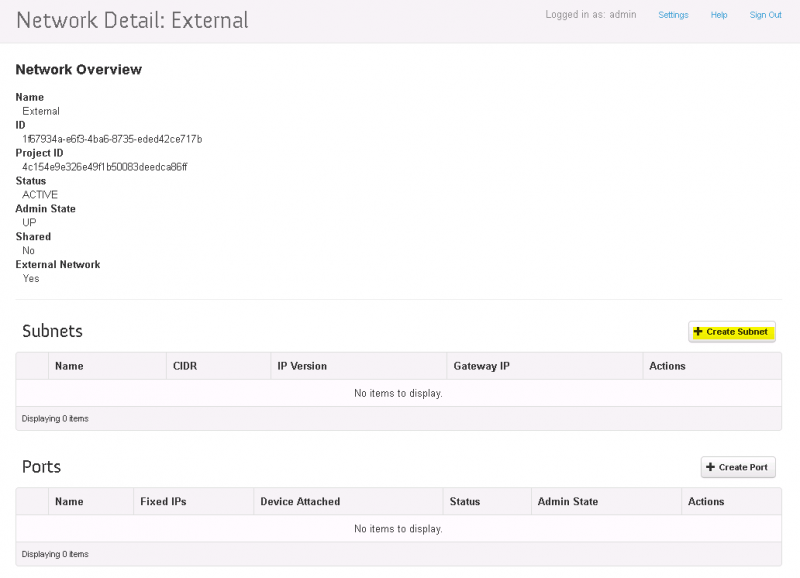
Next click on the network name - here External - to configure additional settings such as the subnet (See Figure 8).

Within the Network Detail view, click on Create Subnet to associate a subnet with this network (See Figure 9).
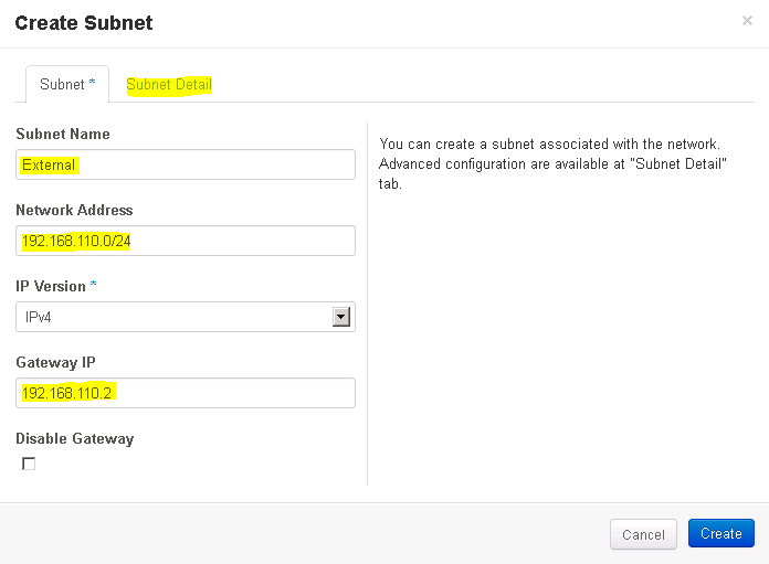
Give the Subnet a meaningful name. I usually use the same name for the Subnet as the Network. Although keep in mind that you can have multiple subnets per network. Furthermore specify the IP range of your external or public network along with the default gateway. In this simple setup, this is the network that all our components (ESXi hosts, vCenter, NSX and VOVA) connect to.
In a realistic, production oriented network, this would be the subnet for the external network that the NSX gateway connects to.
Click on Subnet Detail to continue.
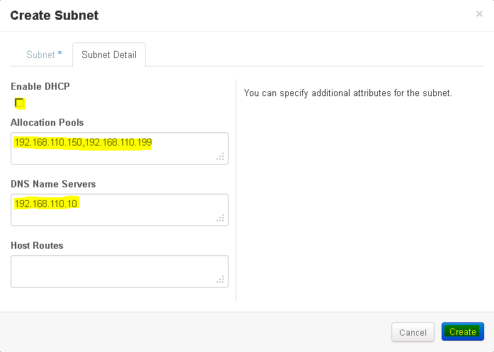
Unselect the Enable DHCP checkbox as this is an external network which either already has an existing DHCP service available, or on which you don’t want OpenStack to supply DHCP capabilities. Specify the Allocation pools specific to your environment with an IP range that is not already in use within the selected subnet. Specify the DNS Name Servers and click Create to finalize the creation of the subnet (See Figure 11).
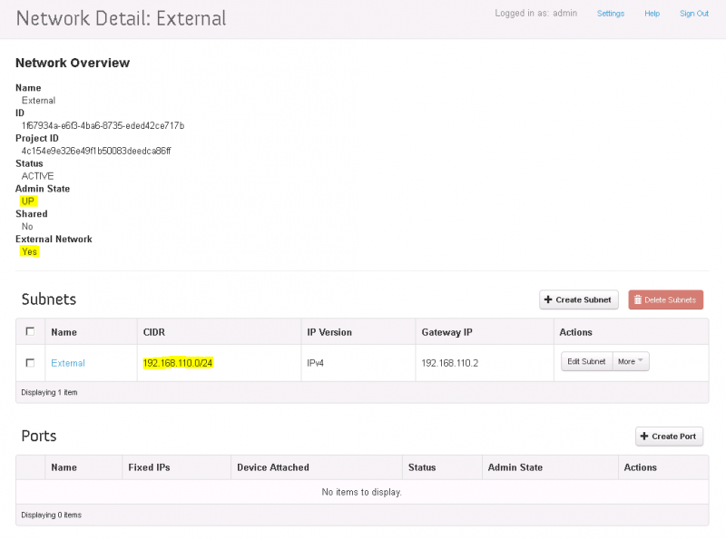
Verify that the external network has been successfully created and is in the UP state (See Figure 12).
Tenant’s view
Creating networks
Let’s return to the tenant’s view and see how the previously created external network will look like. Choose the Project view, then click on the Network Topology tab. You can see the external network available to the tenant (See Figure 13).
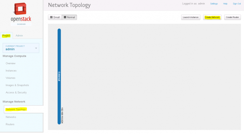
Next we will create the internal network. This task will be completed by the tenant within a project. Therefore still within project view, click on the Create Networks button (See Figure 13).
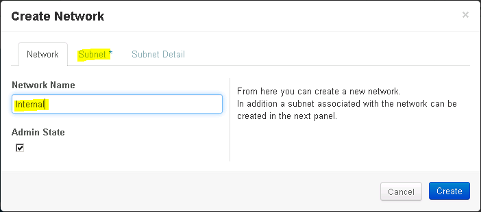
Enter a useful name as the Network Name and click on the Subnet to specify additional information (See Figure 14).
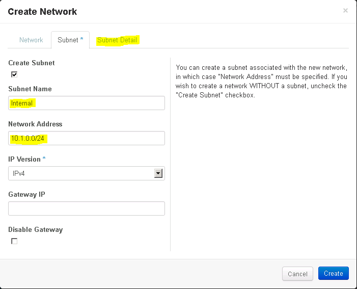
Specify a Subnet Name - e.g. the value Internal - along with the Network Address. Click on Subnet Detail to continue (See Figure 15).
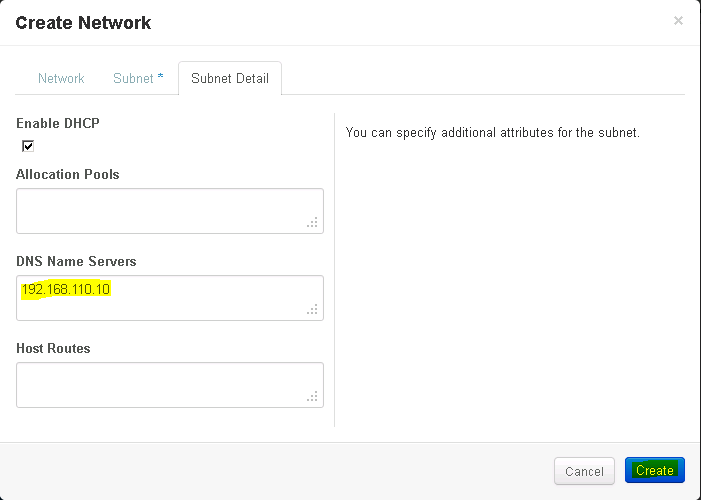
Enter the value of the DNS Name Server and finish the dialog with a click on Create (See Figure 16).
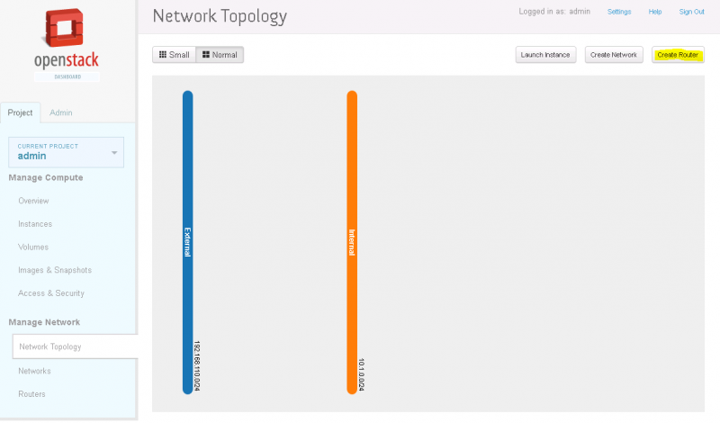
The result is now an external network, which was created and is owned by the cloud administrator and an internal network, which was created and is owned by a project tenant.
But we are not done yet: If we connect a workload to the internal network, it will obviously not have outbound connectivity as internal and external network are not connected. We can fix this by creating a router between the two.
Click on Create Router to get started (See Figure 17).
Give the Router a useful Router Name and finish the creation of the router with a click on Create Router (See Figure 18).

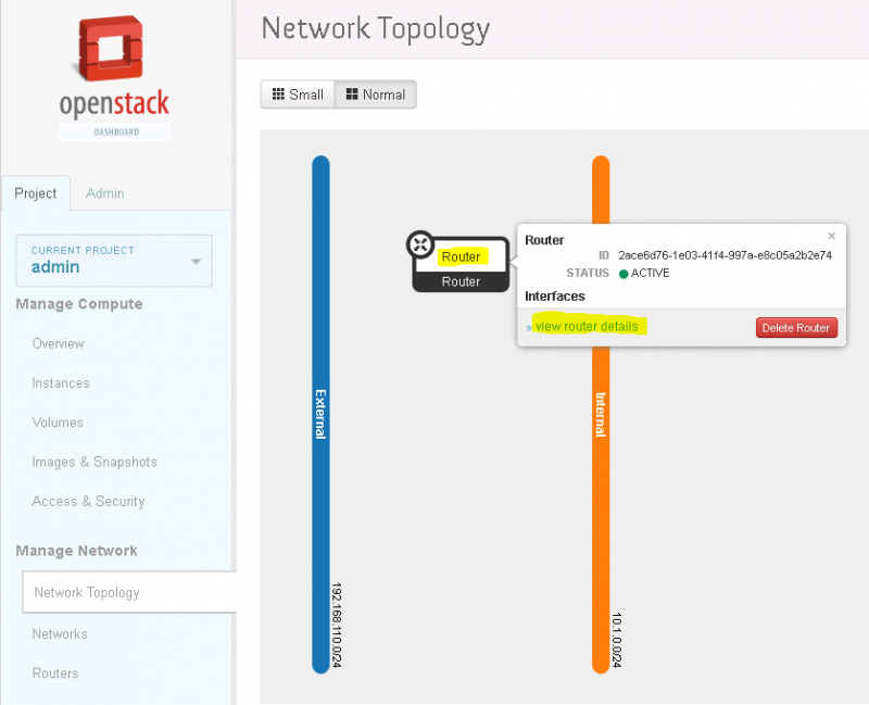
Next we need to create the router’s interfaces on the two networks. Click on the router and choose view router details to get started (See Figure 19).
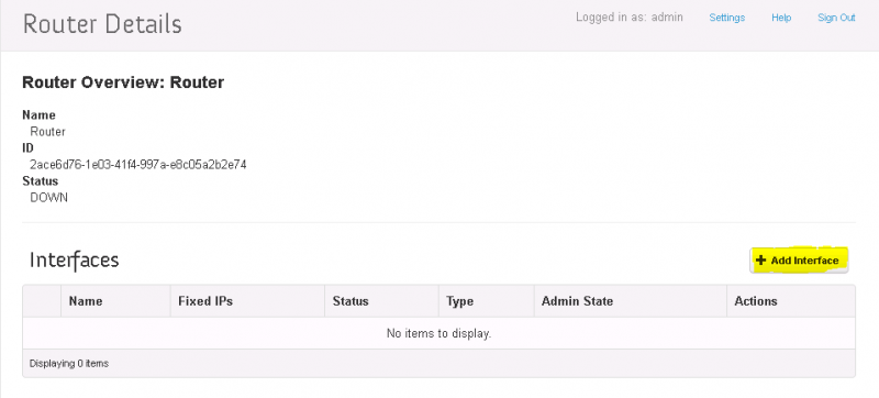
Now click on Add Interface to add the internal interface first (See Figure 20).
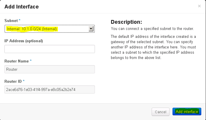
As the Subnet choose the internal network that you created in an earlier step (See Figure 21). In case you are tempted to think that it doesn’t matter which interface we add first: The interface to the external network is an uplink for this router and is therefore added differently. Click on Add interface to finish your selection.
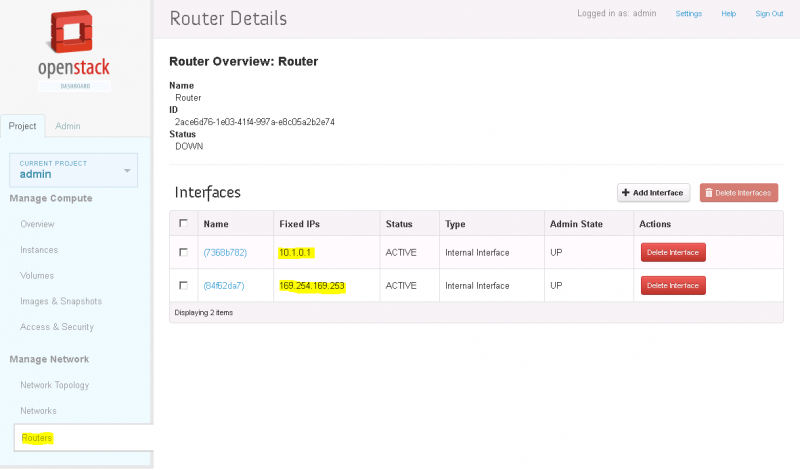
Notice that the result will include an interface with a fixed address from the subnet that is part of the internal network, but also an interface with an IPv4 link local address (See Figure 22). This special interface and address can be used by VMs in OpenStack to query an API in order to learn more about themselves.
Next we need to configure the external network as the upstream network. This is done by setting the gateway for the router. For some reason that capability is not available from within the Router Detail view, adding one more step to our setup.
Click on the Routers tab to leave the Router Detail view (See Figure 22).
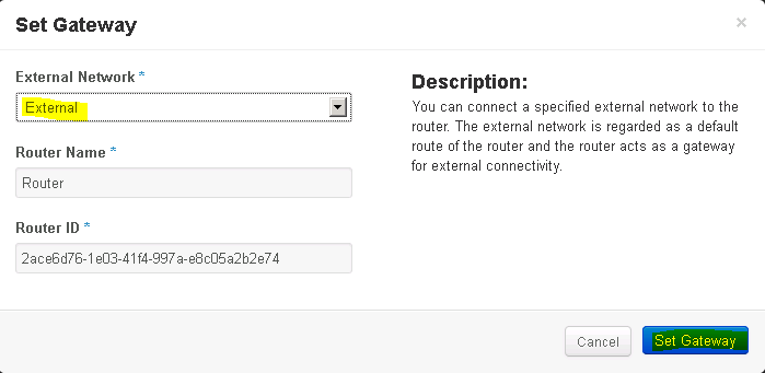
Under Actions for the router click on Set Gateway (See Figure 23).

As the External Network chose the network that is provided by the cloud operator and confirm the selection by clicking on Set Gateway (See Figure 24).
Return to the Network Topology view to see the result (See Figure 25).
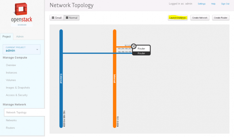
Finally our virtual network in OpenStack as shown in Figure 5 has been completed and we are ready to deploy our first virtual machine.
Deploying a Virtual Machine
Now with the network in place, we are finally ready to deploy a first VM in our OpenStack cloud. From the Network Topology tab click on the Launch Instance button (See Figure 25).
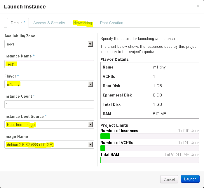
Give your new instance a meaningful name as the Instance Name and select an appropriate Flavor - e.g. m1.tiny. As the Instance Boot Source choose Boot from image and select as the Image Name the image debian-2.6.32-i686 (1 GB), which comes packaged with VOVA. Click on the Networking tab to continue (See Figure 26).
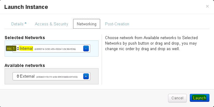
Move the network Internal from the Available networks pool to the Selected networks, by either clicking on the plus icon or using drag-and-drop (See Figure 27).
This connect the internal network that we previously created to the first NIC of the new VM instance. Click on Launch to finalize the creation of your VM instance.
Wait for the new VM instance to be created and powered up. Once the Status indicates Active and the Power State shows running, you’re all set (See Figure 28). The first deployment of a VM instance can take up to a few minutes, as vSphere needs to import the above selected Debian image from VOVA into its local storage. Subsequent deploys will just use a clone of this imported image and are therefore much faster. Click on the name of the VM to see the Instance Detail.

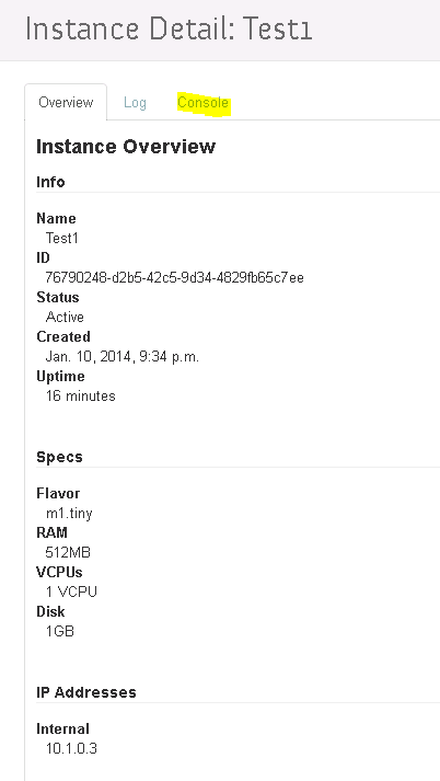
You can see information about the running VM instance - such as the ID, the status or the IP address. Click on the Console tab to connect to the VM (See Figure 29).
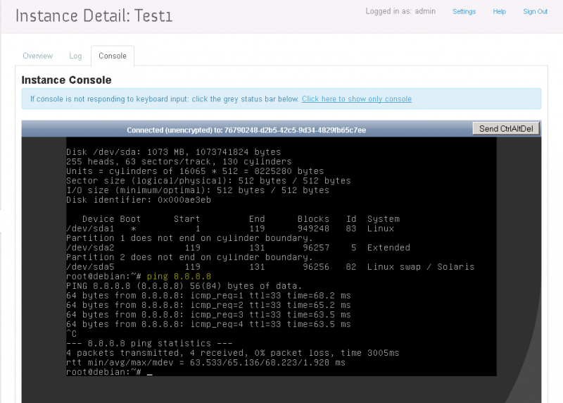
Via the Console you can access your VM instance. Login with the standard username root and the password vmware to this provided Debian image. Afterwards you can control your VM and e.g. test connectivity by pinging the Google Public DNS Resolver at 8.8.8.8 (See Figure 30).
Congratulations! You have gotten your feet wet using your OpenStack cloud, implementing your first virtual network and attaching a new VM instance to it. All this while leveraging VMware vSphere as the underlying Hypervisor as well as network virtualization provided via VMware NSX as a Neutron plugin.
Summary
Next in the series: “OpenStack with vSphere and NSX” on OpenStack with vSphere and NSX is Part 6: “OpenStack with vSphere and NSX – Part 6: Install the VMware vCenter Plugin for Openstack and look behind the scenes” where we will look behind the scenes into VMware vSphere to see what’s happening during the operation of OpenStack on vSphere. We will also install the VMware vCenter Plugin for Openstack to gain more insight into OpenStack from vSphere, as well as use some of the well-known enterprise-class benefits of vSphere - such as VMotion – along with OpenStack. Furthermore we will see how to use OpenStack’s legendary APIs to automate the deployment of a VM.

Leave a comment