Physical networks for VMware NSX
Notice: This article is more than 11 years old. It might be outdated.
During VMWorld 2013 the network virtualization platform VMware NSX was announced by VMware. While there is a plethora of information available on how NSX works or what benefits it brings to the table, the answer on how NSX affects the physical infrastructure remains mostly untouched. Even during various VMWorld presentations this design piece was only covered under the term “Enterprise-class data center network”. Let’s have a look at how the physical underpinning should look like, beyond of what the VMware Network Virtualization Design Guide already states.
Characteristics of Overlay Networks
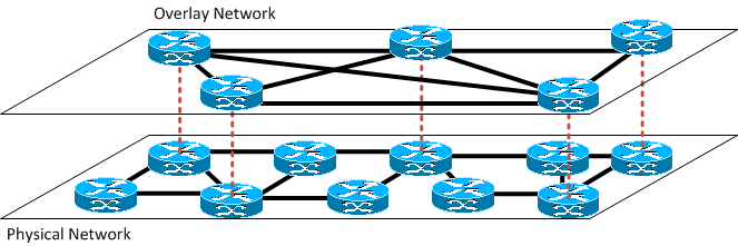
By definition an overlay network is a virtual network of nodes and logical links that is built on top of an existing (physical) network with the purpose to implement a network service that is not available in the existing network. An example of such an overlay network is the Internet itself, which originally provided a packet-oriented network on top of connection-oriented phone lines. Another example is the Multicast Backbone (MBONE) for multicast deployment. Turning this definition upside down, shows us that capabilities not provided by the overlay network need to be provided by the network underneath.

Before we look at some of the missing features of the overlay network in NSX, in order to determine what the physical network needs to provide, let’s look at some of the pain points in today’s data center networks and what NSX attempts to address.
Data Center Network headaches
Today’s network architects have to face the following challenges while designing data center networks:
Fault containment
Spanning Tree is widely considered a risky technology and for many network engineers it’s hard to master it within their data center network and maintain a stable network. IP routing on the other side, while also not trivial to implement, at least provides much better fault isolation in the case that something does go wrong. Simplified speaking: Using IP routing (L3) over switching (L2) increases the chance of not blowing away the entire data center network if something goes wrong.
Traffic isolation and multi-tenant security
Modern data centers - especially in the cloud age - cater to multiple tenants at the same time. Not only does this require separation of network traffic between various tenants, but also separation of tenant traffic from management or storage traffic. The last a data center operator wants, are customers digging into data of other customers. With tenants and workloads changing regularly, it should be able to change this traffic isolation within minutes or second and not days or hours.
Redundancy and efficiency
Last but not least an enterprise class data center network needs to support mission critical workloads. Therefore it needs to have redundancy built-in to support high availability, while at the same time this build-in redundancy shouldn’t be wasted but instead be used in normal operations. Reducing the throughput in a hardware failure scenario is usually a more efficient approach than keeping excess connections in place that only become available during a failure. Here spanning tree by design disables redundant links while routing supports Equal-cost multi-path routing (ECMP), where packet forwarding to a single destination can occur over multiple “best paths”.
NSX to the rescue?
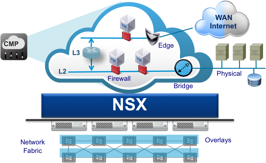
NSX mainly addresses the pain point of traffic isolation and multi-tenant security by offering Overlay networks that can be brought up and down within minutes and include common network services such as Firewalls or Load Balancers. While the usage of VXLAN within NSX e.g. allows physical network designs that are optimized for redundancy and efficiency, it doesn’t enforce them or help with them in any way. This means that even with NSX deployed the underlying physical network needs to be optimized for fault containment, redundancy and efficiency.

Physical network design for NSX
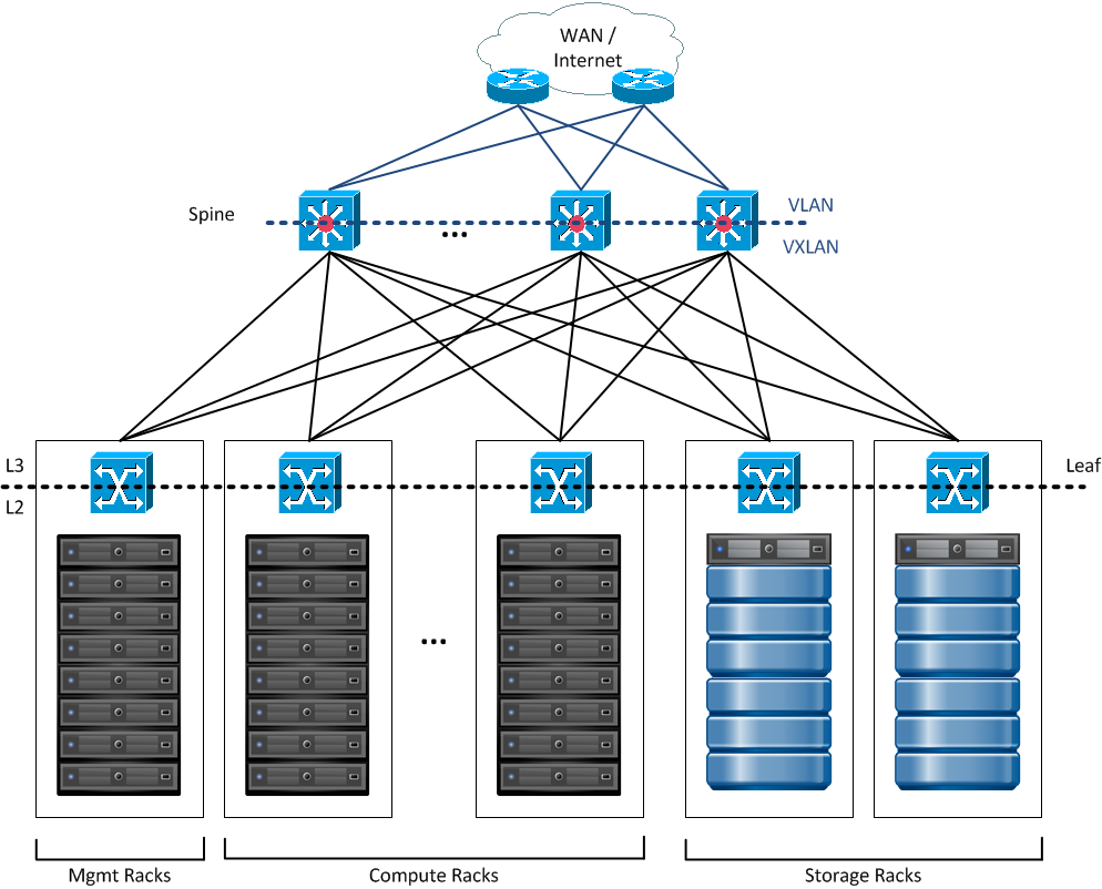
The proposed physical network design is based on the well-known concept of a Spine and Leaf Architecture. Each leaf corresponds to a rack, where the Top-of-Rack (ToR) switches provides L2 connectivity towards the server or storage arrays within the rack. This simple design reduces the requirement for using Spanning Tree to within the rack. Leaf and Spine devices are interconnected via L3 (Routing) and can use the previously mentioned ECMP capability.
Connectivity from within the NSX overlay network to the outside world (WAN or Internet) is provided by VXLAN Tunnel End-Points (VTEP) within the Core layer switches. This capability is e.g. offered by Arista’s Network Virtualization feature. Thus core devices “translate” between VXLAN segments and VLANs.
As an alternative this connectivity can also be provided purely in software - e.g. via an “Edge Rack” - using the Edge devices within NSX.

The resulting physical network proves to be:
- Simple
- Highly scalable
- Provide high bandwidth
- Fault-Tolerant
- Provide optional QoS
An Analogy
Why is the physical network still important in the age of Overlay Networks with VMware NSX? To give an analogy: If you want to provide a reliable and fast logistics service - such as FedEx or UPS - you need reliable streets and roads in good shape for the delivery trucks to run on.
For VMware NSX a solid enterprise class physical network - as outlined above - is therefore necessary.

Leave a comment